Application of X-ray Thickness Gauge in Baosteel 1420 Rolling Mill
Derrick crane, also known as Roof Crane, is a specific style of lifting machine. It is usually a fixed building crane, meaning it is assembled and disassembled in the location where it is used. Generally, the crane is characterized by its long, fixed length tower. These cranes are typically used in locations where items need to be moved from a common initial point to single nearby location, like on shipping platforms and construction sites. BQ models of derrick cranes including 10T Derrick Crane 2533A, 6T Derrick Crane DCB20-6, 10T Derrick Crane DCB24-10, 12T Derrick Crane DCB30-12, 16T Derrick Crane DCB30-16, 18T Derrick Crane DCB42-18.
Roof Derrick Crane,Roof Crane,10T Derrick Crane,Derrick Crane Roof Crane,Building Crane SHEN YANG BAOQUAN BUSINESS CO., LTD , https://www.syconstructionhoist.com
1 System Analysis 1.1 Principle of X-ray Thickness Measurement The attenuation law of X-rays penetrating the material is the theoretical basis of X-ray thickness gauge measurement. The photoelectric sensor transforms the change of the intensity of the radiation into a change of charge that is easy to detect, process and transmit. As shown in FIG. 1, when an X-ray is projected onto a measured object, some of the rays are absorbed by the measured object, and some of the rays pass through the measured object, and the intensity of the rays after passing through the measured substance is, in the case of a certain substance composition, It is related to the thickness and density of the measured object. If the density of the measured object is known, the thickness of the measured substance can be calculated based on the detected ray intensity. X-ray thickness gauge is a thickness measurement system based on the principle of this relationship. 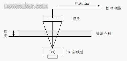
Figure 1 Measuring principle
In the formula, I is the intensity of the attenuated ray detected on the detector, I0 is the initial radiant intensity emitted by the X-ray source, Ï is the density of the measured material, and u' is the mass absorption coefficient of the X-ray material, s The thickness of the material being tested.
1.2 IMS Thickness Gauge System Structure The on-the-spot measurement frame for four thickness gages—C-frames are located in front of and behind a rack, and before and after the 5 racks. The corresponding thickness gauge system devices are named T0, T1, T4, and T5. The thickness value measured by T0 is sent to the basic automatic control system of the rolling mill to participate in the feed forward control; T1, T4 and T5 are located behind the rolling mill and their measured values ​​are involved in the feedback control. The measurement results, measurement accuracy and operation of the 4 thickness gauges The situation will directly affect the rolling mill's precision, product quality and output.
The laser probes of laser speedometers are integrated into the C-frames of T1, T4, and T5. However, the operation, processing, and display of the speedometers are independent of the thickness gauges and can communicate with the thickness gauges through the internal Ethernet network; T1 T4 shares an electrical cabinet (located in the electrical room), which means that the two share processing, storage, and display parts. Regardless of the laser speed measurement on the C-frame in the field, the four thickness gauges have the same system configuration, network structure, and signal processing flow. The following uses T0 as an example to illustrate. 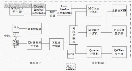
T0 system structure shown in Figure 2.
The probe senses the X-ray intensity and converts it into a current signal (10-12~10-7A). It is amplified by a measuring transducer and converted into a digital signal and transmitted to the instrument control room via fiber optic media via industrial Ethernet. After the transmission medium is converted into Category 5 twisted pair, it is connected to the internal network switch of the system, and the data is finally obtained by the M-Client computer. The M-Client obtains the digitized thickness measurement value and performs a series of calculations. The processed digital quantity is used for the software display and control in the M-Server computer, and is observed through the V-Client display; the other channel is converted into an analog quantity and output. The field bus Interbus analog module, and finally to the PLC of the rolling mill control system. At the same time, the status of the thickness gauge is sent to the rolling mill PLC, and the setting data for control is received from the rolling mill PLC, including the rolling target thickness value, steel roll number, and so on.
The high voltage generator supplies cathode negative high voltage and filament current required for the X-ray tube to emit X-rays. The X-ray controller controls the high voltage and filament current provided by the high voltage generator through the serial port, and obtains the current through measurement feedback data lines. Actual values ​​for the tube current, high voltage, filament current, etc. are used for condition monitoring and control. These data are output by the serial port of the ray controller and converted to an RJ-45 interface via a COM-Server interface converter. The data is then sent to the internal network switch so that it can be displayed and controlled on the software in the M-Server.
The thickness measurement system auxiliary I/O signal is transmitted using the fieldbus, and the Interbus bus of the company PhoenixContact is used. The status signals such as the presence or absence of high pressure, shutter status, C-frame position, and whether the cooling water temperature flow exceeds the limit are transmitted to the industrial control processor M-Client of the instrument control room via the fieldbus Interbus, and the M-Client within the aforementioned M-Server. The software is displayed for monitoring and processing.
The Q-Server computer is used for long-term storage of large amounts of data and statistical analysis of data. It is equipped with a SQL Server database and data display and analysis software. The Q-Client display is used to display Q-Server content. Mass storage and data statistics of the data not only adapt to the needs of the production process, but also help the long-term maintenance of the thickness gauge. As a gateway, NAT32 is used to convert the thickness meter TCP/IP protocol and Siemens H1 protocol and communicate with two networks to complete the transmission of setting data, measurement data, and status data.
1.3 Network Structure of Thickness Gauge The transmission, measurement results and status of measurement data from the field to the instrument control room are called by the software inside the M-Server, the measurement data is stored in the Q-Server database, the measurement data deviation and the digital signal of the thickness gauge status Sending, setting data reception, communication between thickness gauges, etc. are all realized through the network. If the network of the rolling mill control system that communicates with the thickness gauge system is understood as the external network, the connection between the various devices of the thickness gauge system is achieved through the internal Ethernet network. As shown in Figure 3. 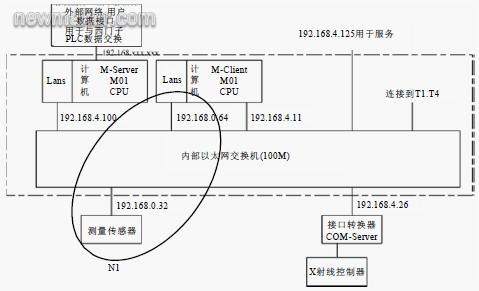
Figure 3T0 network structure
Inside the thickness gage system, the communication network and its terminals are called MEVInet, which is an abbreviation of "Measuring and visualization network" and is a standard automation system network developed by IMS and registered. The system meets common technical standards and provides maximum transparency between software and hardware. Therefore, the network performance is stable and the communication speed is fast (100 MB/s). It is easy to expand and it is very convenient to maintain. MEVInet consists of 4 subsystems:
1MEVInet-M (measurement, control, management functions)
-M-Server
-M-Client
2MEVInet-V (display, monitor function)
-V-Client
3MEVInet-Q (Quality Management Function)
-Q-Server
-Q-Client
4MEVInet-N (communication connection function)
-Switch
-EthernetCard
-5UTPandFiber
MEVInet-N established a communication link and formed three internal subsystems such as MEVInet-M, MEVInet-V, and MEVInet-Q into an internal LAN.
1.4 Instrument Characteristics The system uses the MXR161 type of cermet tube, the maximum withstand high pressure is 160KV; the high pressure generator model is HSG101, which can provide high voltage of 100KV. Under normal working conditions, the system uses a tube high voltage of about 80KV and a tube current of 3.0mA, so that the ray tube can work in the 1/2 of the maximum withstand voltage for a long time, which can effectively prolong the service life of the ray tube. The normal service life of the tube can reach 4 to 6 years.
T0 used four ionization chambers of the same type KG20/20 as probes. The high voltage of each ionization chamber used 1200V, and the maximum output current of the ionization chamber was about 100000pA.
The on-site measurement device uses a C-frame, which is driven by an electric motor from the "standby" position to the "measurement" position and is free to move. The action of the shutter and internal standard plate is driven by a force balance system consisting of compressed air and a spring mechanism to achieve shutter opening and IN/OUT of the standard plate. The X-ray tube is cooled with the secondary circulation cooling water and the cooling water circulation control system is designed by itself. Thickness meter system parameters are shown in Table 1.
Table 1 thickness gauge system parameters 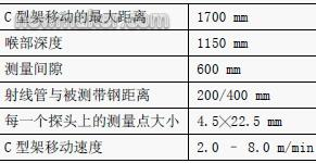
1 The tested material is carbon steel and high-strength steel plate;
2 measuring range 0.1~4.0mm;
3 linear ≤ ± 0.05%;
4 time constant 1.4ms (Figure 4);
5 Repeatability (2σ) ≤ ± 0.1%;
6 drift short-term drift ≤ ± 0.05%, long-term drift (8 hours) ≤ ± 0.1%;
7 Statistical noise (2σ) ≤ ± 0.1% (under conditions with a total effective time constant of 10 ms). 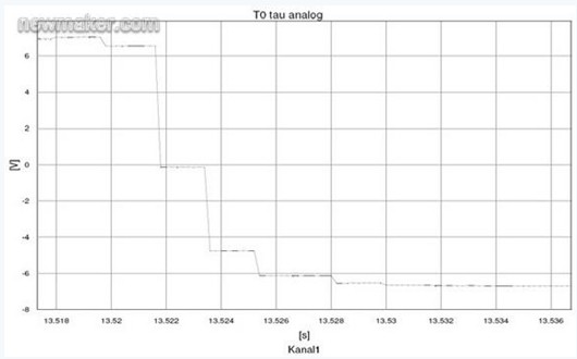
Figure 4T0 time constant 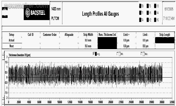
Figure 5 Long-term drift test 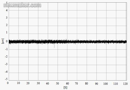
Figure 6 noise curve
The thickness measurement system uses low-noise, long-life, and stable X-ray sources, inert gas ionization chambers, optical fiber transmission media, and field bus technologies. It utilizes a highly integrated and powerful industrial computer (M-Client). Data signal processing. The application of a series of advanced technologies has greatly improved the accuracy and stability of measurement, effectively reduced the number of points of failure, and reduced the intensity of daily inspection and maintenance work. Although higher levels of integration reduce system complexity and failure points, it also introduces the high cost of major replacement of spare parts. In addition, the high price of the system itself has added some limitations to its application.
References 1 Xie Zhongxin, et al. X-ray spectral analysis. Science Press, 1982.
2 German IMS Corporation. Operating Manual. Equipment Information, 2006.(end)
