The knowledge about gears is explained in shallow and deep (I)
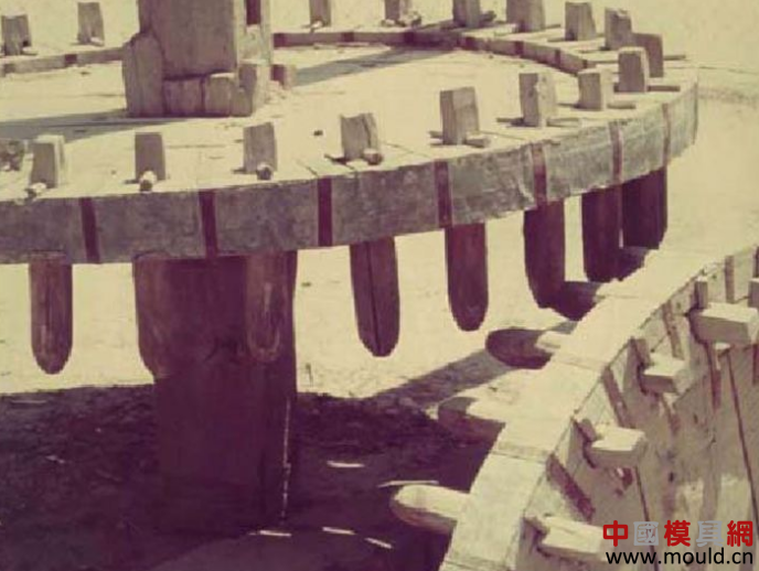
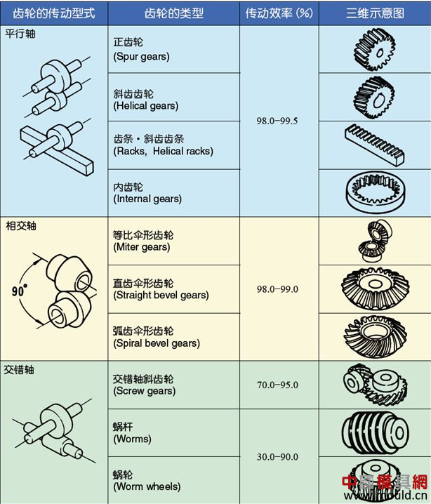
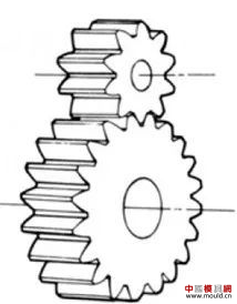
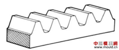
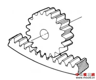
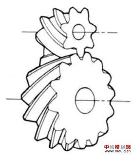
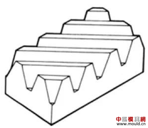
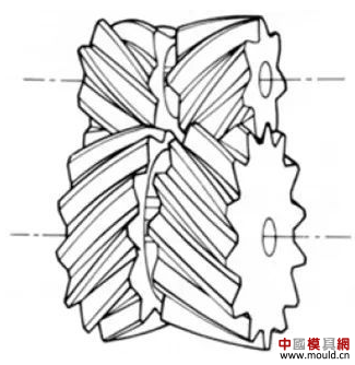
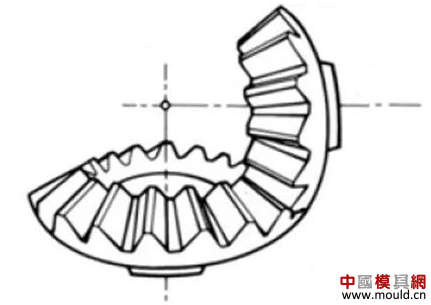
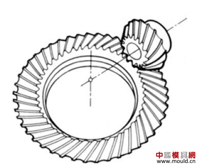
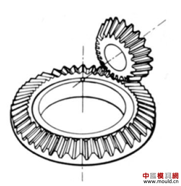
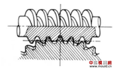
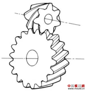
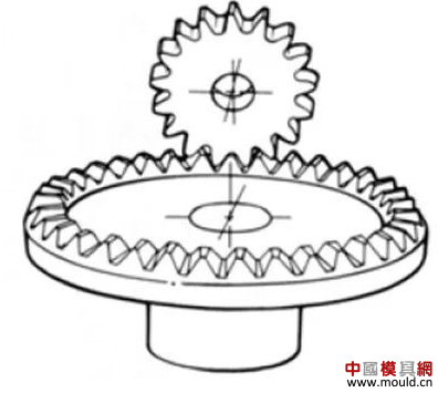
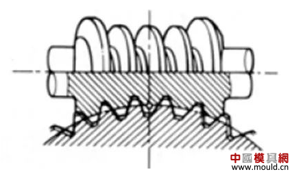
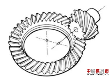
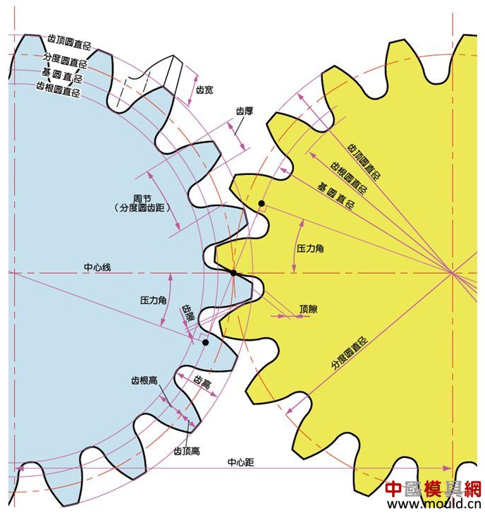
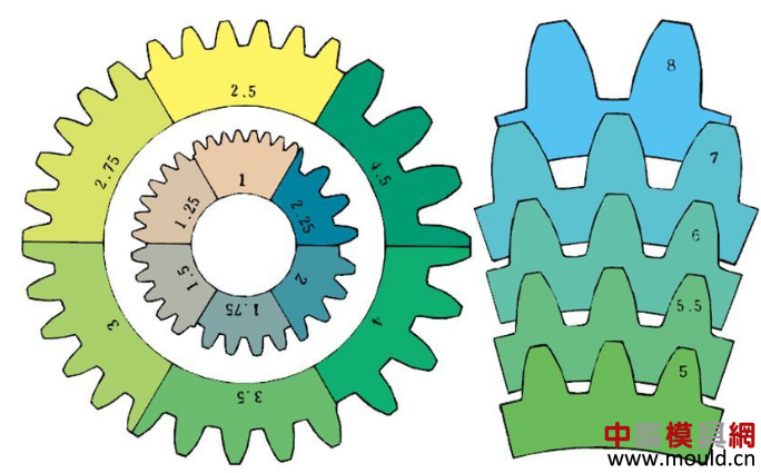
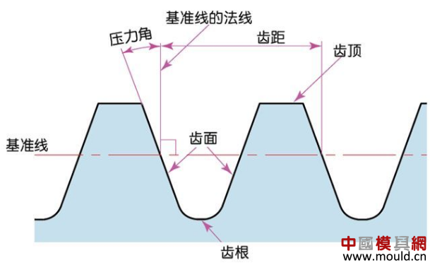
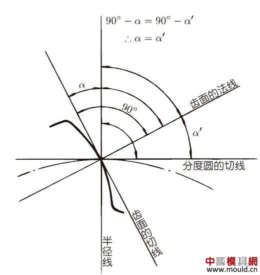
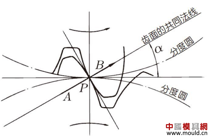
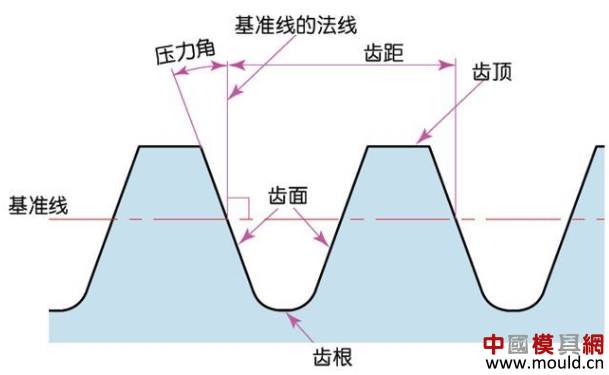
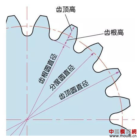
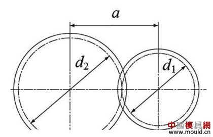
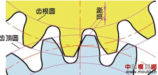
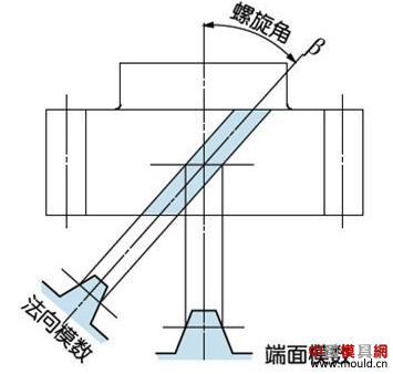
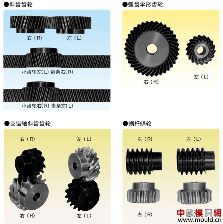
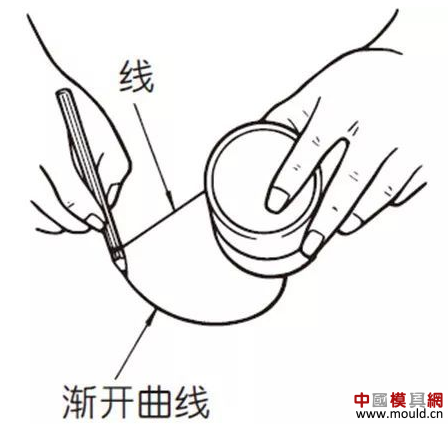
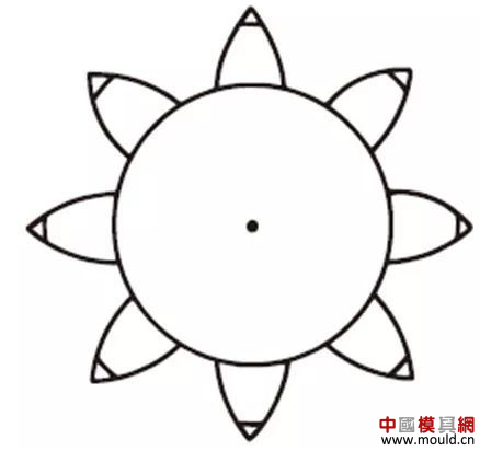
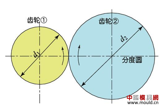
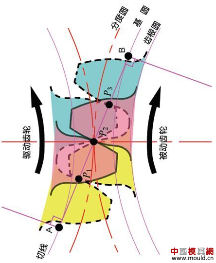
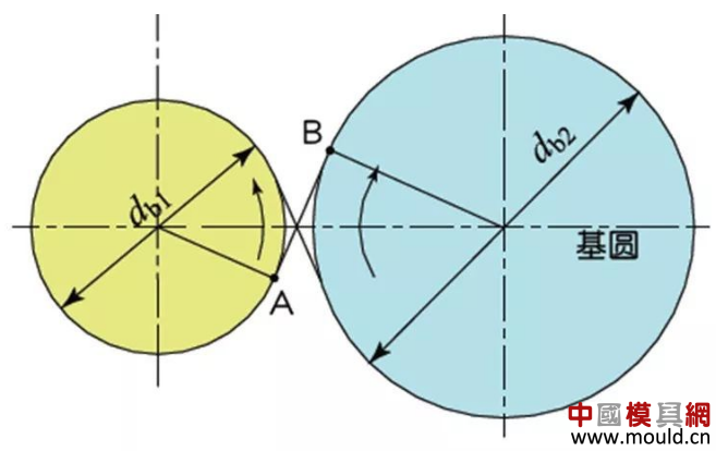
1. What is a gear? Gears are toothed mechanical parts that can mesh with each other. It is used in a wide range of applications in mechanical transmission and in the entire mechanical field. 2. History of gears As early as 350 BC, the famous Greek philosopher Aristotle recorded the gears in the literature. Around 250 BC, the mathematician Archimedes also described the hoist using a worm gear in the literature. The gears of BC are still preserved in the remains of Kate Sven in Iraq today. The history of gears in our country has also a long history. According to historical records, the gears were used in ancient China from 400 to 200 BC. The bronze gear unearthed in Shanxi, China is the oldest gear ever discovered. As a guide car reflecting the achievements of ancient science and technology, it is a gear mechanism. As the core mechanical device. In the second half of the 15th century, during the Italian Renaissance, the famous all-rounder Leonardo Da Vinci not only left an indelible achievement in the history of gear technology in the field of culture and art, after more than 500 years, now The gear still retains the prototype of the sketch at the time. It was not until the end of the 17th century that people began to study the shape of the teeth that correctly transmitted motion. In the 18th century, after the European industrial revolution, the application of gear transmission became more and more extensive; first, the cycloidal gear was developed, and then the involute gear was used. Until the beginning of the 20th century, the involute gear had already occupied an advantage in the application. Later, displacement gears, circular gears, bevel gears, helical gears, and the like were developed. Modern gear technology has been achieved : gear module 0.004-100 mm; gear diameter from 1 mm to 150 m; transmission power up to 100,000 kW; speed up to 100,000 rpm; maximum peripheral speed of 300 m / s. Internationally, power transmission gear units are developing alongside miniaturization, high speed, and standardization. The application of special gears, the development of planetary gears, the development of low-vibration, low-noise gears are some of the features of gear design. 3. Gears are generally divided into three categories. There are many types of gears, and the most common classification method is based on the gear shaft. Generally divided into three types: parallel axis, intersecting axis and staggered axis. 1) Parallel shaft gears: including spur gears, helical gears, internal gears, racks and helical racks. 2) Intersecting shaft gears: Straight bevel gears, spiral bevel gears, zero-degree bevel gears, etc. 3) Interlaced shaft gears: There are staggered shaft helical gears, worm gears, hypoid gears, etc. The efficiency listed in the above table is the transmission efficiency, excluding the loss of bearings and mixing lubrication. The meshing of the gear pairs of the parallel shaft and the intersecting axis is basically rolling, and the relative sliding is very small, so the efficiency is high. Interlaced shaft gears such as crossed helical gears and worm gears are driven by relative sliding to achieve power transmission. Therefore, the influence of friction is very large, and the transmission efficiency is reduced compared with other gears. The efficiency of the gear is the transmission efficiency of the gear under normal assembly conditions. If the installation is not correct, especially if the bevel gear assembly distance is incorrect and there is an error with the intersection of the cone, the efficiency will be significantly reduced. 3.1 Parallel shaft gears 1) Spur gear A spur gear in which the tooth line and the axis line are parallel. Because it is easy to machine, it is the most widely used in power transmission. 2) Rack A linear rack gear that meshes with a spur gear. It can be seen as a special case when the pitch diameter of the spur gear becomes infinite. 3) Internal gear A gear that meshes with the spur gear and is machined on the inner side of the ring. Mainly used in applications such as planetary gear transmissions and gear couplings. 4) Helical gear The spur gear with the tooth line being a spiral. Because it is stronger than the spur gear and runs smoothly, it is widely used. Axial thrust is generated during transmission. 5) Helical rack, a bar gear that meshes with a helical gear. This is equivalent to the case where the pitch diameter of the helical gear becomes infinite. 6) Herringbone gear The tooth line is a combination of two helical gears that are left-handed and right-handed. There is an advantage that no thrust is generated in the axial direction. 3.2 Intersecting shaft gear 1) Straight bevel gear A bevel gear in which the tooth line is aligned with the bus bar of the pitch line. In bevel gears, they are of a type that is relatively easy to manufacture. Therefore, it is widely used as a bevel gear for transmission. 2) Spiral bevel gear The tooth line is a curved, bevel gear with a helix angle. Although it is more difficult to manufacture than straight bevel gears, it is also widely used as a high-strength, low-noise gear. 3) Zero bevel gear Curved bevel gear with a helix angle of zero. Because of the characteristics of both straight and curved bevel gears, the tooth surface is subjected to the same force as the straight bevel gear. 3.3 Interlaced shaft gear 1) Cylindrical worm pair The cylindrical worm pair is a general term for a cylindrical worm and a worm gear that meshes with it. Quiet operation and single pair can achieve the biggest feature of the large transmission ratio, but it has the disadvantage of low efficiency. 2) Interlaced helical gears The name of the cylindrical worm pair when it is driven between staggered axes. It can be used in the case of a helical gear pair or a helical gear and a spur gear pair. Although the operation is stable, it is only suitable for use under light load. 3.4 Other special gears 1) Face gear A disc gear that can mesh with a spur or helical gear. Drive between the orthogonal axis and the staggered axis. 2) Drum worm pair The general term for a drum worm and a worm gear that meshes with it. Although it is difficult to manufacture, it can drive a large load compared to a cylindrical worm pair. 3) Hypoid gears A conical gear that is driven between staggered shafts. The large and small gears are eccentrically machined, similar to the spiral gears, and the meshing principle is very complicated. 4. Basic terminology and size calculation of gears Gears have many terms and expressions specific to gears. In order to give everyone more insight into gears, here are some basic terms used in gears. 1) The name of each part of the gear 2) The term indicating the size of the teeth is the modulus M1, m3, m8... are called modulus 1, modulus 3, and modulus 8. Modulus is a universal term for the world. The symbol m (modulo) and the number (mm) are used to indicate the size of the teeth. The larger the number, the larger the gear teeth. In addition, in countries where the English unit is used (for example, the United States), the size of the gear teeth is indicated by the symbol (diameter) and the number (the number of teeth of the gear when the index circle diameter is 1 inch). For example: DP24, DP8, etc. There are also special calling methods that use symbols (weeks) and numbers (mm) to indicate the tooth size, such as CP5, CP10. The pitch (p) is obtained by multiplying the modulus by the pi, and the pitch is the length between adjacent teeth. Expressed by the formula is: p = pi × modulus = πm Comparison of tooth sizes of different modules: 3) Pressure angle The pressure angle is a parameter that determines the tooth profile of the gear. That is, the inclination of the tooth surface. The pressure angle (α) is generally 20°. Previously, gears with a pressure angle of 14.5° were once popular. The pressure angle is the angle between the radius line and the tangent of the tooth shape at a point on the tooth surface (generally a node). As shown, α is the pressure angle. Since α' = α, α' is also the pressure angle. When the meshing state of the A tooth and the B tooth looks from the node: The A tooth pushes point B on the node. The driving force at this time acts on the common normal of the A and B teeth. That is to say, the common normal is the direction of force, and the direction of pressure, and α is the pressure angle. The modulus (m), the pressure angle (α) plus the number of teeth (z) are the three basic parameters of the gear. Based on this parameter , the dimensions of each part of the gear are calculated. 4) Tooth height and tooth thickness The height of the teeth is determined by the modulus (m). Full tooth height h=2.25m (= tooth root height + tooth tip height) The height of the crest (ha) is the height from the crest to the index line. Ha=1m. The root height (hf) is the height from the root to the index line. Hf = 1.25 m. The reference for the tooth thickness (s) is half the pitch. s = πm/2. 5) diameter of the gear The parameter that determines the size of the gear is the index circle diameter (d) of the gear. Based on the indexing circle, the pitch, tooth thickness, tooth height, tooth height and root height can be determined. Index circle diameter d=zm Tip circle diameter da=d+2m Root diameter df=d-2.5m The index circle is not directly visible in the actual gear because the index circle is a circle assumed to determine the size of the gear. 6) Center distance and backlash When the indexing circle of a pair of gears is tangentially engaged, the center distance is half the sum of the diameters of the two indexing circles. Center distance a=(d1+d2)/2 In the meshing of the gears, the backlash is an important factor in order to achieve a smooth meshing effect. The backlash is a gap between the tooth faces when a pair of gears mesh. There is also a gap in the tooth height direction of the gear. This gap is called the Clearance. The headspace (c) is the difference between the root height of the gear and the height of the tooth tip of the mating gear. Headspace c=1.25m-1m=0.25m 7) Helical gear The gear that has been helically twisted by the teeth of the spur gear is a helical gear. Most of the spur gear geometry can be applied to helical gears. Helical gears are available in two ways depending on their reference plane: End face (axial right angle) reference (end face modulus / pressure angle) Normal (tooth right angle) reference (normal modulus / pressure angle) The relationship between the end modulus mt and the normal modulus mn mt=mn/cosβ 8) Spiral direction and coordination Helical gears, spiral bevel gears, etc., the gear teeth are spiral gears, and the spiral direction and fit are fixed. The spiral direction means that when the central axis of the gear points upward and downward, when viewed from the front, the direction of the teeth points to the upper right is [right-handed], and the upper left is [left-handed]. The cooperation of various gears is as follows. 5. The most common gear tooth profile is the involute profile Simply dividing the pitch of the aliquots on the outer circumference of the friction wheel, attaching the protrusions, and then meshing with each other, the following problems occur: The tangent point of the tooth produces a slip The speed of the cut point is fast and slow. Produce vibration and noise The gear teeth are both quiet and sleek, thus creating an involute curve. 1) What is the involute Wrap a thread with a pencil on one end on the outer circumference of the cylinder, and then gradually release the thread in a state of tightness in the line. At this point, the curve drawn by the pencil is the involute curve. The outer circumference of the cylinder is called the base circle. 2) 8-tooth involute gear example After aliquoting the cylinder 8, eight pencils were attached and eight involute curves were drawn. Then, the wire is wound in the opposite direction, and eight curves are drawn in the same manner. This is a gear having an involute curve as a tooth shape and a number of teeth of 8. 3) Advantages of involute gears Even if there is some error in the center distance, it can be correctly engaged; It is easier to get the correct tooth shape and it is easier to process; Because the rolling engagement on the curve, the rotational motion can be smoothly transmitted; As long as the teeth are the same size, one tool can machine gears with different numbers of teeth; The roots are thick and strong. 4) Base circle and division circle The base circle is the base circle that forms the involute profile. The index circle is the reference circle that determines the size of the gear. The base circle and the index circle are important geometric dimensions of the gear. The involute profile is a curve formed on the outside of the base circle. The pressure angle on the base circle is zero degrees. 5) Engagement of involute gears The indexing circles of the two standard involute gears are tangentially meshed at a standard center distance. When the two wheels are engaged, the appearance looks like the two circular friction wheels with the diameter of the indexing circle d1 and d2. However, in practice the engagement of the involute gear depends on the base circle rather than the index circle. The meshing contact points of the two gear teeth are moved on the meshing line in the order of P1 - P2 - P3. Please pay attention to the yellow teeth in the drive gear. The gear is engaged by two teeth (P1, P3) for a period of time after the tooth begins to engage. Engagement continues, and when the engagement point moves to point P2 on the index circle, only one of the meshing teeth remains. Engagement continues, and when the engagement point moves to point P3, the next tooth begins to engage at point P1, again forming a state in which the two teeth are engaged. As such, the two-tooth engagement of the gears alternates with the single-tooth engagement to impart rotational motion. The common tangent line A-B of the base circle is called the meshing line. The meshing points of the gears are all on this meshing line. It is represented by an image diagram, just as the belts are placed over the outer circumference of the two base circles to make a rotational motion to transmit power. Printing Packing List Envelope Printing Packing List Envelope,High Quality Printing Packing List Envelope,Printing Packing List Envelope Details, CN AM-Besten Technology Ltd. , https://www.bestenpack.com