How to solve the foam fire truck transmission shaft imbalance failure?
Fault Diagnosis and Remedy: Check whether the driveshaft of foam fire truck is sunken. If there is a sag, the fault will cause the south; if there is no sag, it will continue to check. Check if the balance plate of the drive shaft tube falls off. If it falls off, the fault is caused by this; otherwise continue checking. Check that the telescopic fork is installed correctly. If it is not correct, the fault is caused by this; otherwise, continue inspection. Remove the propeller shaft for dynamic balance test. If the motion is unbalanced, it should be calibrated to eliminate the malfunction. If the bend should be straightened. How to assemble the drive shaft. The method of installation of the drive shaft is as follows: Grease the foam fire truck universal joint bearings with grease or gear oil, match the oil seal, and put them on the cross shaft, press the front and rear drive shaft end joint yoke, telescopic clevis and flange respectively. Fork hole towel, then install the cover and lock ring, tighten and lock. Apply grease to the propeller shaft expansion sleeve, then place the fork on the spline shaft of the rear propeller shaft and tighten the oil seal cap. Connect the front drive shaft flange fork to the second shaft flange of the transmission, and install the front drive shaft on the middle support frame of the drive shaft. Then bolt the ten bytes on both ends of the rear drive shaft to the front drive shaft and On the flange of the rear axle driving gear shaft, tighten the flange fixing bolts and nuts. Transmission spline sheath and cross shaft nipple must.
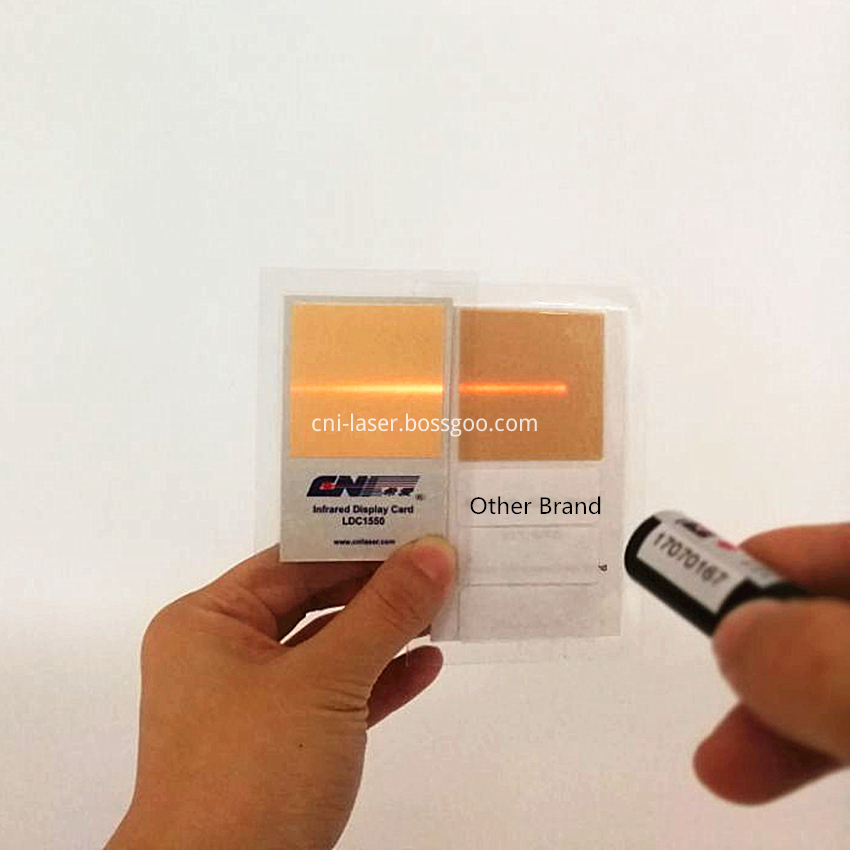
IR Laser viewing cards convert infrared radiation to visible radiation providing a visual image of infrared light. The cards consist of an infrared phosphor material which stores the energy from conventional light sources (e.g. indoor room lighting, sunlight). As incident infrared light stimulates the phosphor, the stored energy is released in the form of visible light.Hand-held infrared viewers are ideal for observation and alignment, of Laser beams with wavelengths between 800 and 1550 nm. The viewer delivers a bright, high-contrast image with edge-to-edge sharpness.
Specifaications of Plastic IR Viewer
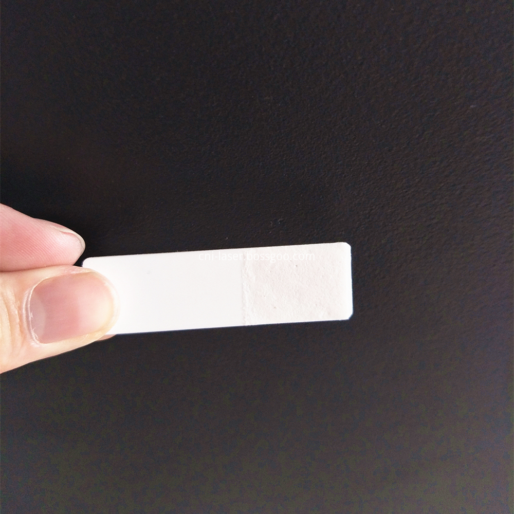
Specifications of Ceramic IR Viewer
1. YAG / Fiber Laser adjustment
2. IR laser and LED beam test
Laser Viewing Card,Ir Viewing Card, Ceramic IR Viewer,Plastic IR Viewer Card Changchun New Industries Optoelectronics Technology Co., Ltd. , https://www.lasersciences.com

Wavelength Range
800-1500nm
Nodel Number
LDC-1550-25
LDC-1550-40
Active Area
25 x 25 mm
40 x 40 mm
Peak Emission
610-635 nm
Sensitivity @ 1000 nm
6 mW/ cm^2
Sensitivity @ 1300 nm
60 mW/ cm^2
Sensitivity @ 1500 nm
>500 mW/ cm^2
Pulse Damange Threshold
0.05
CW Damange Threshold
10
Card Dimensions (mm)
33 x 55
45 x 70

Wavekength Range
900-1100nm
Model Number
LDC-1100
Peak Emission
540-548 nm / 651-666 nm
Active Area
20 x 15mm
Sensitivity 2 1064 nm
>20 mW/ cm^2
CW Damange Threshold (kW/ cm^2)
10
Bass Plate
Precision ceramic material
Application
Dimension (mm)
15 x 15
